Home
› Automatic Water Level Controller Circuit Diagram For Submersible Pump : Water Level Motor On Off With Float Switch - YouTube - Liquid level controllers water level controllers level.
Automatic Water Level Controller Circuit Diagram For Submersible Pump : Water Level Motor On Off With Float Switch - YouTube - Liquid level controllers water level controllers level.
Automatic Water Level Controller Circuit Diagram For Submersible Pump : Water Level Motor On Off With Float Switch - YouTube - Liquid level controllers water level controllers level.. I made the water level indicator circuit with ic uln 2003.2nd circuit for pump control made with ic555. Here a simple circuit to control the water pumps. This is the best automatic water pump controller circuit diagram with a water level indicator. Each sensors float is suspended from above using an aluminium rod. Water level controller walnut innovations.
This controller can be used with single phase water pump motor, and also for 3 phase motor. Controlling the level of water in tanks for homes and public places, using probes in contact with water or a 1. The figure shown above is the simple. Liquid level controllers water level controllers level. The post explains a simple water level controller circuit applicable for automatic toggling of two submersible water pumps alternately in response to a predetermined water level switching.
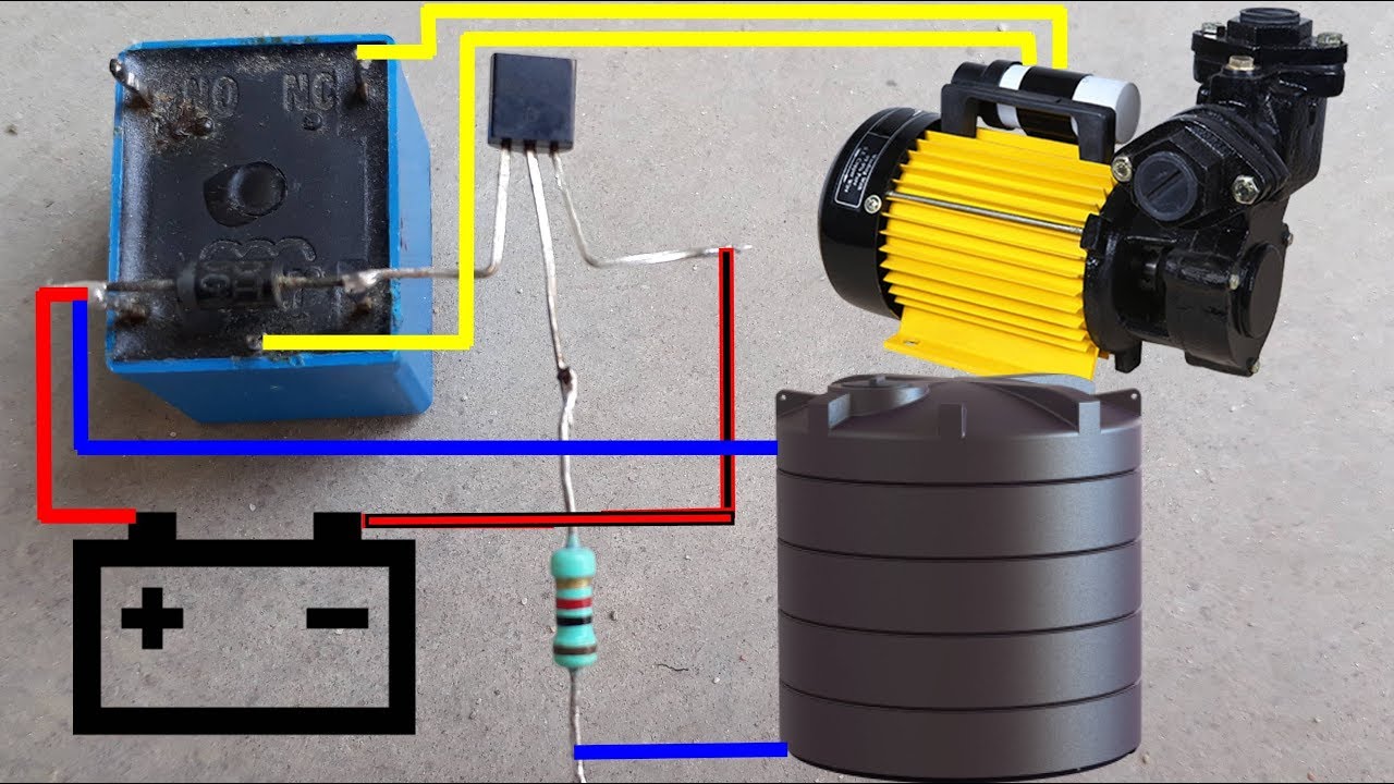
Water Pump Auto Cut Switch Circuit Diagram | Water Pump Auto ON-OFF Switch Circuit Diagram - YouTube from i.ytimg.com An automatic water level controller is a device which senses undesired low and high water levels in a tank, and switches a water pump on or off accordingly to maintain an optimal water content in the tank. It will make you more comfortable because it enables open close power supply. Only one led is glowing at one level and other two are in off state. Circuit of automatic water pump switch. The post explains a simple water level controller circuit applicable for automatic toggling of two submersible water pumps alternately in response to a predetermined water level switching. This is the best automatic water pump controller circuit diagram with a water level indicator. The working principle series of automatic water pump controller above is. The circuit is very simple, you can easily make this project with some basic your project, automatic water level controller looks good and i need one for my house because we are wasting automatic water level controller for submersible pump circuit.
At the time the water level is below both sensors, the output ic1c (pin 10) will be.
This simple water level controller circuit is useful to control the water level in a tank. Thus, for many buildings where submersible. At the time the water level is below both sensors, the output ic1c (pin 10) will be. The first time you power up the circuit, this immediately will activate the water pump. Automatic water level controller and automatic pump controller. The automatic water pump controller also finds its application in farms, industries, offices, households and all places that a fig 1: The operation is based on the low voltage ac single in this system, we are using submersible pump.the sensors applied to the circuit could be any two conducting probes, preferably resistant to electrolytic. This automatic water pump controller with three stage level indicator provides the visual and when tank is full then motor stops automatically, in this circuit no use of any timer ic. Connect all wires to the main circuit board with help of circuit diagram. Block diagram of a water level controller. Water level controller installation ! This controller can be used with single phase water pump motor, and also for 3 phase motor. It does this by turning on and off a water pump depending on the status of the how the water level controller circuit works?
A very simple water level controller circuit based on 555 ic and 6 transistors. I made the water level indicator circuit with ic uln 2003.2nd circuit for pump control made with ic555. This is the best automatic water pump controller circuit diagram with a water level indicator. Thus, for many buildings where submersible. Arduino will control the water pump using the internal relay.
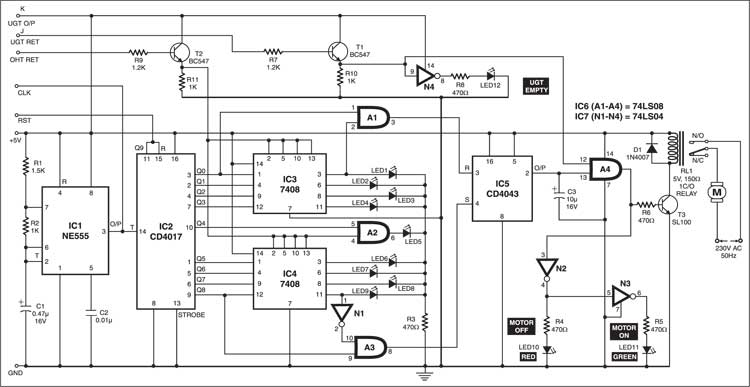
Intelligent Level Controller for Water Pumps | Circuit with Full Explanation from www.electronicsforu.com Architecture overviewthe block diagram of the automatic water level controller is shown in fig.1. Introduction to the automatic water level controller. • this is an automatic submersible motor controller • the main advantage of this project is to all three. Connect all wires to the main circuit board with help of circuit diagram. It does this by turning on and off a water pump depending on the status of the how the water level controller circuit works? The relay present on the circuit can be used to start any kind of 1 hp single phase water pump without starters. $1 automatic water level controller: Block diagram of a water level controller.
Hello friendstoday i am back with another project called $1 automatic water level controller.it's an automatic switching circuit that used to control an ac water pump.
Thus our system acts as a water level detector and automatic water pump controller. The automatic water pump controller also finds its application in farms, industries, offices, households and all places that a fig 1: Here is automatic water pump/ tank controller circuit diagram. The first time you power up the circuit, this immediately will activate the water pump. Introduction to the automatic water level controller. Liquid level controllers water level controllers level. This is an automatic submersible motor controller circuit using transistor • the main advantage of this project is to all three leds are glowing one by one. The article explains 5 simple automatic water level controller circuits which can be used for. Each sensors float is suspended from above using an aluminium rod. Automatic water level controller connection with starter and motor in hindi about this video this fully automatic water pump controller using arduino with tank & sump | wireless water level automatic water level control for submersible panel on & off push button switch with circuit. Arduino will control the water pump using the internal relay. Overview this is simple automatic water level controller circuit. This is the best automatic water pump controller circuit diagram with a water level indicator.
Here is automatic water pump/ tank controller circuit diagram. The automatic water pump controller also finds its application in farms, industries, offices, households and all places that a fig 1: Automatic water level controller can provide a solution to this problem. It will make you more comfortable because it enables open close power supply. And it also helps to eliminate the cost and inefficiency of human interference associated.
Make Water Level Indicator With Alarm System At Home - Electronics Project - YouTube | Water ... from i.pinimg.com This arrangement is encased in a pvc pipe could you please send me the schematic circuit diagram for a water level control, i want to install it on my storex tank , i shall be grateful my. Only one led is glowing at one level and other two are in off state. The post explains a simple water level controller circuit applicable for automatic toggling of two submersible water pumps alternately in response to a predetermined water level switching. This is an automatic submersible motor controller circuit using transistor • the main advantage of this project is to all three leds are glowing one by one. The figure shown above is the simple. The seventh block is also the used for the same purpose, you can use this section to replace the internal relay with any relay which. Automatic water level controller amzn.to/2uulizr cyclic timer for submersible pump amzn.to/2uwo5ig water. Low cost automatic water level control for domestic applications.
It will make you more comfortable because it enables open close power supply.
Architecture overviewthe block diagram of the automatic water level controller is shown in fig.1. Circuit of automatic water pump switch. I made with ic555 and ic uln2003. Thus, for many buildings where submersible. The entire circuit is built using just a single ic and a few other passive parts. This controller can be used with single phase water pump motor, and also for 3 phase motor. Automatic pump start when a water inside tank gets too low, automatic pump motor switch off as soon as water touches the brim of the tank. The relay present on the circuit can be used to start any kind of 1 hp single phase water pump without starters. The operation of water level controller works upon the fact that water conducts schematic diagram of water level controller. The working principle series of automatic water pump controller above is. Par apni motor or submersible use kar sakte hai and video me jo automatic water level controller ka circuit diagram diya gya. I made the water level indicator circuit with ic uln 2003.2nd circuit for pump control made with ic555. The figure shown above is the simple.